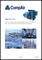
CompAir 5442 Compressor Block
The unit is of reciprocating design with single acting cylinders. It is of conventional oil lubricated design and is a water cooled machine.
[wds id=”1″]
As with all other CompAir water cooled compressor units, the 5442 is a robust unit that is suitable for continuous operation. All major castings are of either SG or conventional grey iron for maximum strength and durability.
| Click Image To View PDF | Click Image To View PDF | Click Image To View PDF |
|---|---|---|
 |
 |
 |
Quick Facts:
– 250 CFM @ 3,000 PSI
Compressor Performance:
Compressor delivery pressure… ………. 3000 psig (206 bar g)
Compressor speed (nominal)…. ………. 1800 rpm
Compressor output………………. ………. 250 cfm ***
Compressor shaft power (approx) 195 hpNote ***The capacities illustrated above are free air delivered figures, based on measurement at 1.013barAbs and 20°C standard test conditions. Tolerances on capacity and power will be in accordance with tables illustrated in ISO1217: 1996.
Compressor Package Features
Compressor Drive
The compressors block would be supplied with flywheel and flexible drive coupling.
- Inlet suction filter / silencer
Compressor instrument panel with:
- Pressure gauges for each stage
- Oil pressure gauge
- Combined temperature indicator and cut-out protection switch on final delivery
- Relief valves on each compressor stage
- Water cooled inter & after-coolers on all stages
- Water cooled, crankcase oil cooler
- Automatic water valve fitted on cooling water inlet connection
- Mechanical separators fitted at all stages
- Stage condensate drain valves
- Solenoid valve to operate unloading system
- Oil cooler
- All unloader drains will be piped to a common drain connection point
Forced lubrication system comprising:
- Oil pump
- “Spin-on” replaceable oil filter
- Low oil pressure protection switch
- Crankcase oil filler
- Crankcase oil level sight glass
- Crankcase breather
- Non-return valve on final delivery
Compressor Cooling
The water requirements for the compressors will be approximately 7350 l/hr in order to give sufficient cooling to the compressors.
The cooling water supply to the booster should be as cool as possible, clean and particle free. The water supply should have a maximum supply pressure of 5 bar g and maximum approach water temperature of 35°C.
It would be necessary for manual isolating valves to be put into the water inlet &outlet lines at the time of installation for maintenance purposes. Any isolating valve installed at the inlet to the machine should be capable of throttling the water flow to achieve a nominal 10 to 12°C temperature rise through the compressor for optimum operating conditions. If required thermometers can be provided on the cooling water inlet and outlet connections to allow monitoring of the cooling water supply / return lines.
| ASC Compair 5442 Compressor Block | Downloads |
| CompAir 5442 Compressor Guide | |
| CompAir 5442 Specifications Sheets | |
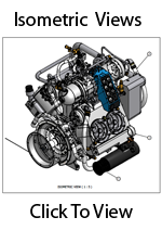
| CompAir 5442 Isometric Views |